
After ignoring it for a while, I decided to look into repairing it. I have taken off quite a few old soldered valves inside the house, but I have always replaced them with valves that have compression fittings. This was different because I was going to have to remove the twisted copper pipe and replace it with a new pipe, so in lieu of replacing the tee and possibly more parts, soldering was the only real option.
So as I often do, I went to the Internet and found some simple instructions on eHow. This guy's video told me everything I really needed to know.
http://www.ehow.com/video_4767454_sweat-copper-pipe-fittings.html
I already had a propane torch and standard tools, but I bought the new parts, plus a wire tubing brush and lead-free flux and solder. I have cut copper pipe with a hack saw before with good results (just have to be very careful not to crush it), so I didn't buy a pipe cutter. Here are all the assembled parts and tools.

The original spigot was soldered onto the copper pipe directly with the threads on the outside. I bought an adapter so that the new spigot could be removed and replaced without soldering if it begins to leak.

Soldering the adapter onto the tube was really easy. Since I had the spigot attached to it (giving me something to hold onto), the spigot got pretty hot and the paint on the handle bubbled a bit. But since the spigot is threaded on, I can just unscrew to replace it if it wears out faster from getting too hot.

Next came the really difficult part, removing the old spigot. If you watched the video, you will remember that you want everything to be dry so that you can get the parts hot enough. This turned out to be really important, and it also turned out to be impossible, because the main valve below the tee was also leaking very slowly. So I had a slow drip coming out of the spigot.
If you imagine a pot of water heating on a stove top, when you get the pot and the water to 212 ºF, the water boils off as steam. Since there is only a certain amount of water in the pot, when it all boils off, the pot quickly gets hotter than 212 ºF if enough heat is being applied. In this case, I essentially had an unlimited pot of water. When the temperature got hot enough, it boiled out of the spigot, but there was more cool water filling the tee from behind because it was leaking through the valve below. Water has a tremendous heat capacity (unlike metals), so it takes a lot of heat to raise the temperature of water. This is the concept behind things like automobile radiators; just keep running cool water through your engine and it will not overheat. But since I was trying to get the soldered joint up to 350 - 840 ºF (probably closer to the high end of that range) and the trickle of water was trying to keep it down around 212 ºF, I simply could not make enough headway to melt the old solder.

So I went to the main valve by the street and closed it also, then I bled out the pressure from the valve below the tee. And it still leaked. The leak was much slower, so I tried again with the torch. I adjusted the flame and moved it around to try to apply the strongest possible heat to the joint. After a while, I could tell that it was finally about to start melting because a stray speck of solder on the surface of the pipe turned silvery. So I kept at it and used my adjustable pliers to try to twist the spigot free. The spigot actually came free from the tube before the tube came free from the tee, even though I was applying heat directly to the spot where the tube met the tee. I had a brief moment of anxiety that I wouldn't be able to remove the tube from the tee without damaging the tee and creating a bigger job, but it eventually twisted free also.
The total time spent on removing the old spigot and tube was probably close to an hour, which accounted for the bulk of the job. I was fairly surprised that I never ran out of propane.

The last step was to solder the new tube into the tee. There was still a slow drip of water to complicate matters, and I was only able to apply the flux to the tube and not the tee, which was too wet inside, so I made sure there was plenty of flux on the tube. With my recent practice at using the flame with high effectiveness, the soldering wasn't as bad as the removal had been, although it did take a bit longer than the dry soldering I had done earlier. Since I was barely able to get to the temperature I needed, the final result was also much less even and clean. You can see some beads of solder that fell onto the concrete drip catcher below the assembly.
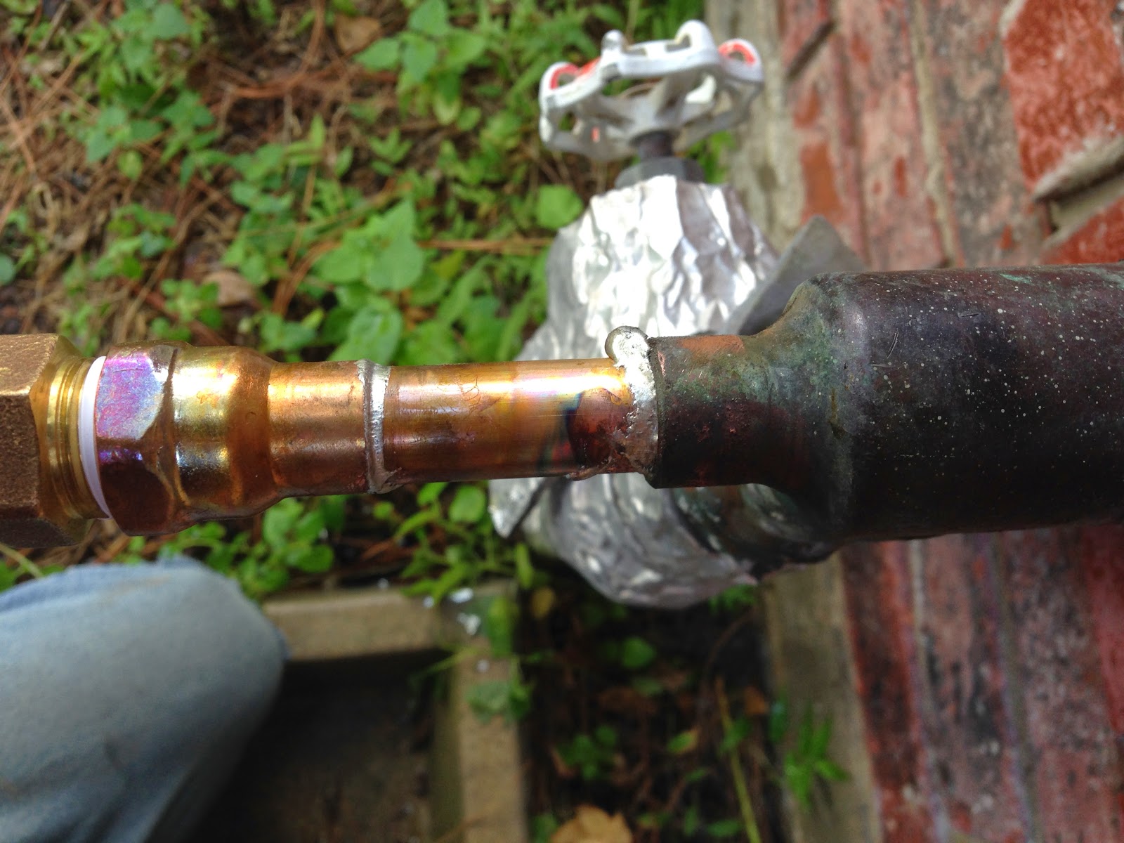
But it does the two things it is supposed to do: it doesn't leak, and it holds the pipe together. So the solder definitely worked its way into the joint. So far, so good! And now I know how to solder a copper pipe, and I have learned the importance of working with dry parts.


